Bridging real measurements to idealized ones
Today is about physical measurement, reverse engineering, and most importantly, measurement (error).
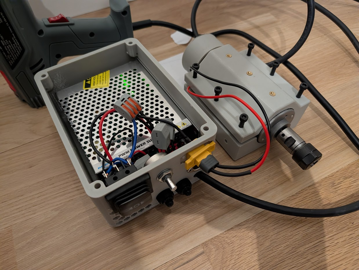
A couple of weeks ago, I mentioned that I had been working on another weird little project on my extended break. The basic idea was this: I happened to stumble upon a small Youtuber who was sharing a simple 3d printed machine he had designed for doing jewelry and lapidary work. Essentially it was a single CNC router spindle mounted to a 3d printed plastic box that held the power supply and supporting controls. The basic design was simply the spindle in a clamp attached to the top of a box that held the power supply. There are various mounting points and features on the box to extend the functionality.
Most importantly, the guy was developing a series of interesting 3d printed accessories that interface with the base machine. Since the machine is just a motor with an ER16 workholding collet on the end, it can spin all sorts of small and not-so-small shaft tools for various uses. Accessories included a 4-inch lapidary saw (which costs about $400 new), various grinding/sanding/sharping attachments. The spindle can also drive a belt and be used as a generic power source for other spinning tools like a micro-sized lathe.
Suffice it to say, I could really use a small lapidary saw for about $300 in various parts that could also double as a bunch of other weird little crafting machines I need for my oddjob projects. And most importantly, someone had gone through all the work of looking at suppliers and parts and had a list of materials I can go quickly buy, and a wiring diagram that's easier to read than a mis-translated spec sheet. So I donated a few dollars to the project, got a plan, put the whole thing together in about a week.
And then, I realized that the motor used carbon brushes and no one in the supporter community has any idea what brushes it used. So I volunteered to open up the motor to see what brushes we needed to buy... and promptly cracked the brush assembly on re-assembly. *facepalm
While I could just buy a second motor and reuse all my work, I didn't like the idea of having a tool with a known finite life in the brushes. Luckily, the same supplier has a more expensive brushless version of the motor that cost about $80 more. Since brushless motors are generally better than brushed ones on a bunch of parameters, I decided that despite the dimensions of both the motor and power supply were different from the original, I'm gonna build a new system that's compatible with the old machine's accessories.
And with that long exposition, we're into today's data topic – measuring stuff for reverse engineering. Any scientist who's done field work can now proceed to roll their eyes at me because I'm going to be stating the obvious, but it bears repeating for folks like myself who spend the VAST amount of our time measuring abstract objects that we create by definition, we are typically not used to handling measurement error outside of weird missing/duplicated data biases.
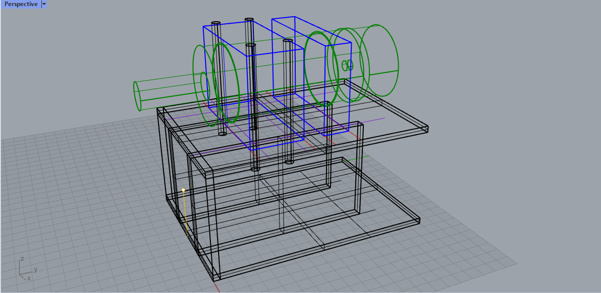
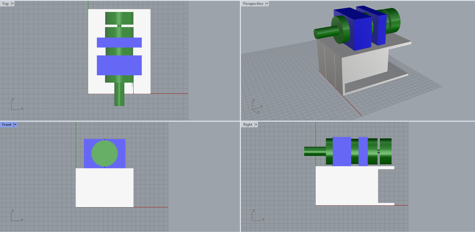
For this new project I needed to model out the a 3d printed case to interface with actual physical objects. That means walls have actual thickness dimensions, interfaces for slots and screws need actual tolerances to allow for proper fit despite part and printer errors. Most critically, since my 3d printed parts will use screws and bolts to attach to the hardware, I need to accurately locate the features so they align with the physical objects.
For example, the power supply has three screw holes that accept M4 screws - metric screws that have a nominal shaft diameter of 4mm including the outside of the thread. I need to place 3 holes that will allow those M4 screws to pass through and link my part to the power unit. The only way to do that is to take a bunch of detailed measurements off various reference surfaces. The edge of "Hole 1" is 9.5 mm from the back, the diameter of the hole is 4.2mm, so the center must be near 11.6 mm, right? In theory that's how the math should work out.
But when I go to use my digital and dial calipers to take these measurements, I run into physical reality. First measurement comes in at 9.38mm, try again and get 9,47, Oh, I might be holding things a bit crooked so let's gently rotate the measurement to find the minimum – 9.30. Oh, I might've used too much force taking the measurement, what if I use a lighter but still-firm touch so the steel caliper jaws don't bite into the softer aluminum – 9.33. Oh, there's a curved bevel so make sure to avoid that when measuring.
It's pretty obvious (and expected) that the last decimal place on the calipers is highly unreliable. But life isn't as simple as ignoring the last decimal place. The tool itself has enough flex in it that if I used too much force while taking a measurement, I could easily nudge a dimension off by maybe 0.05mm, often enough to risk rounding something up or down. And those 0.1mm differences actually do matter. going 0.1-0.2mm in either direction can mean a part fitting snuggly, loosely, or not at all. This whole flex thing is exactly why micrometers which are designed to measure down to 0.001 mm dimensions can come with built in ratchets that will click and stop pushing when they hit a certain consistent amount of force. Otherwise operator error can easily overcome any accuracy gained from using the tool.
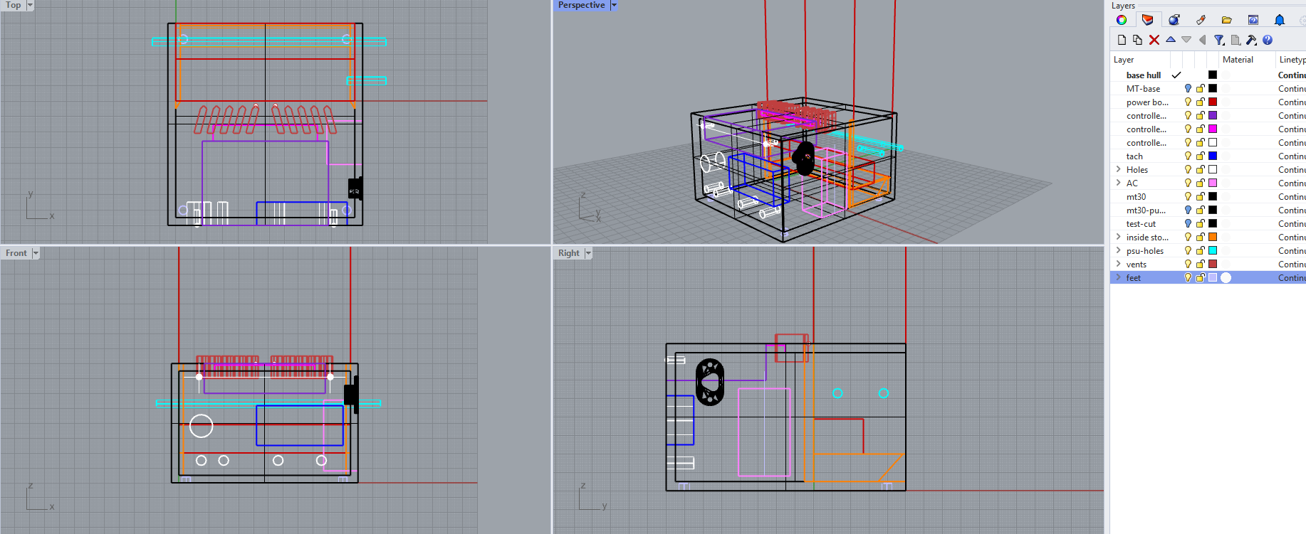
Anyways, that's a lot of measuring and re-measuring for one pesky hole. Now repeat all this for every switch, plug, circuit board and connector. Once you have all the measurements taken you can head over to some CAD software and model out the case with all the penetrations. My experience is that the CAD part goes surprisingly quickly once you have confident measurements. I had my prototypes ready in maybe 2 hours at the computer versus spending over 6 hours fiddling with calipers and rulers.
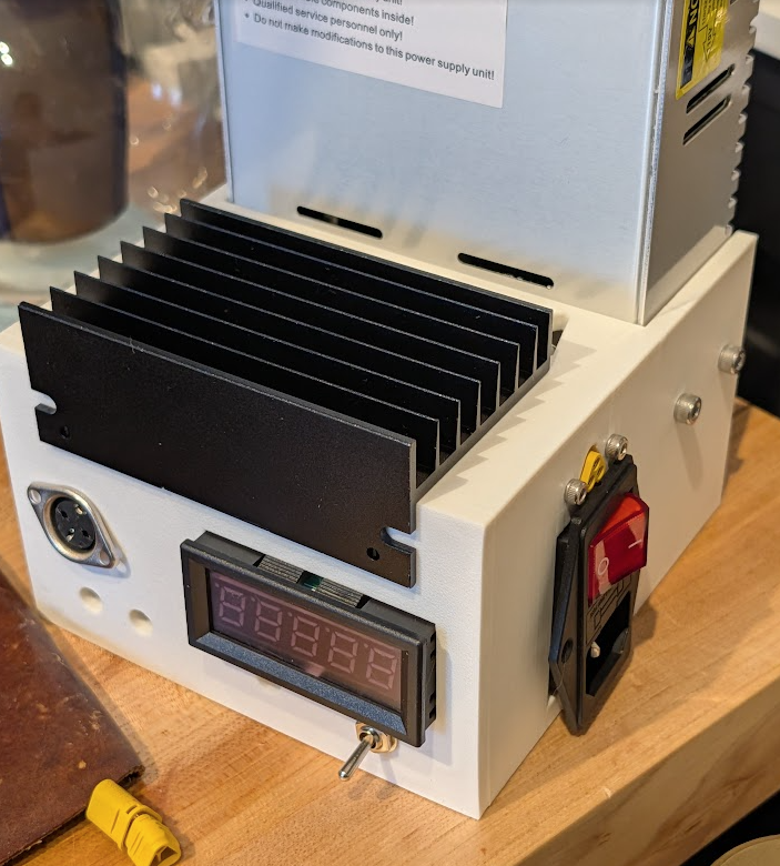
Then, you finally use some plastic by sending the design to the 3d printer. After eight hours of printing you get your first prototype case! Luckily, on my first try I actually did manage to locate the holes correctly! But aside from those three holes, literally no other parts in the kit fit into the designed spots – not a single switch, connector, or anything. Because I had forgotten to add extra space for clearances.
So I had to go and re-measure all the parts that didn't fit and compare them to the physical print, then go back and adjust everything by a millimeter here or there. The second prototype was much more successful, allowing parts to slip in for a test fit. There were a couple of small bugs to fix but a definitely improvement.
A similar process goes for the spindle mount, except in order to build in compatibility with the original's set of accessories, I had to reverse engineer the locations of various mounting holes – and the original design was by an American who was clearly using customary units. All the measurements I were taking were bizarre numbers like 9.2mm, 38mm, 11.2mm. 135.3mm. I had to go find a "metric to nearest fractional inch" conversion tool to make a guess as to what the original intended dimension was. For a few of the important dimensions, I still can't figure out what justification the original designer used. Maybe there wasn't any intention at all. I dunno.
I still have a couple more nights of CAD work to be done before I can finish this project. Then I'll have another tool on my bench that will enable some more fun.
But hopefully this project can act as a bit of inspiration on data collection. Even something seemingly simple like figuring how "how big something is" can get extremely involved. Makes you remember that a lot of the abstractions we measure every day aren't nearly as clean and simple as we pretend.
Standing offer: If you created something and would like me to review or share it w/ the data community — just email me by replying to the newsletter emails.
Guest posts: If you’re interested in writing something, a data-related post to either show off work, share an experience, or want help coming up with a topic, please contact me. You don’t need any special credentials or credibility to do so.
"Data People Writing Stuff" webring: Welcomes anyone with a personal site/blog/newsletter/book/etc that is relevant to the data community.
About this newsletter
I’m Randy Au, Quantitative UX researcher, former data analyst, and general-purpose data and tech nerd. Counting Stuff is a weekly newsletter about the less-than-sexy aspects of data science, UX research and tech. With some excursions into other fun topics.
All photos/drawings used are taken/created by Randy unless otherwise credited.
- randyau.com — homepage, contact info, etc.
Supporting the newsletter
All Tuesday posts to Counting Stuff are always free. The newsletter is self hosted. Support from subscribers is what makes everything possible. If you love the content, consider doing any of the following ways to support the newsletter:
- Consider a paid subscription – the self-hosted server/email infra is 100% funded via subscriptions, get access to the subscriber's area in the top nav of the site too
- Send a one time tip (feel free to change the amount)
- Share posts you like with other people!
- Join the Approaching Significance Discord — where data folk hang out and can talk a bit about data, and a bit about everything else. Randy moderates the discord. We keep a chill vibe.
- Get merch! If shirts and stickers are more your style — There’s a survivorship bias shirt!